Standard OBD-II diagnostic trouble codes (DTCs) used by manufacturers to identify vehicle problems. These are generic codes — manufacturers may use different codes for the same fault. This list is for reference only.
Note: B codes (B1200–B1499) are believed to be GM-specific. C codes from C1211 onwards are GM/Chevrolet/GMC specific.
Understanding DTC Code Structure
Powertrain
Engine, transmission, fuel system, ignition, and emissions-related codes.
Network
CANBus and communication faults between control modules.
Body
Body electronics — door locks, windows, wipers, climate control.
Chassis
ABS, traction control, steering, and suspension systems.
What is a DTC?

The DTC value helps narrow down the specific component or module in question. A DTC has a standardised format — the first character is the Alpha Designator which indicates the system affected:
- B — Body electronics (door locks, hood latches, windows)
- C — Chassis (traction control, ABS, steering)
- P — Powertrain (engine, transmission, fuel system)
- U — Network communications between control modules
The second digit indicates whether the code is generic (0) or manufacturer-specific (1–9). The OBD-II specification reserves the first 1,000 entries in each category as a core set uniformly implemented across all manufacturers.
DTC Type Definitions
| Type | MIL Behaviour | Clearing Condition |
|---|---|---|
| Type A | MIL illuminates immediately on first occurrence | MIL off after 4 consecutive clean drive cycles. History DTC clears after 40 warm-up cycles without fault, or via scan tool. |
| Type B / E | MIL illuminates after 2 (or 3) valid drive cycles with the fault present | Same as Type A — 4 clean cycles for MIL off, 40 warm-up cycles or scan tool for history DTC. |
| Type Cnl | MIL does not illuminate — fault recorded in freeze frame only | History DTC clears after 40 warm-up cycles without fault, or via scan tool. |
| Type Z | DTC present in software but disabled — diagnostic does not run, MIL never illuminates | N/A |
Clearing Trouble Codes
Important: Do not clear DTCs unless directed to do so by the relevant service procedure. When DTCs are cleared, Freeze Frame and Failure Record data that may help diagnose an intermittent fault will also be erased.
If the fault has been corrected, the ECM will automatically count warm-up cycles and clear the DTC from memory. To manually clear DTCs, use a diagnostic scan tool.
Note: The ignition key must be OFF when disconnecting or reconnecting power to the ECM (battery cable, ECM connector, fuse, jump leads etc.) to prevent ECM damage.
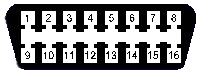
OBD-II Connector Pinout (SAE J1962)
The standard 16-pin OBD-II diagnostic connector is located within 60cm of the steering wheel. Not all pins are used in every application.